The flow capacity of API6A gate valves is a critical factor in various industrial applications, particularly in the oil and gas industry. As a reputable API6A gate valve supplier, we understand the importance of providing high - quality valves with well - defined flow characteristics. In this blog, we will explore what the flow capacity of API6A gate valves is, the factors influencing it, and how it impacts industrial operations.
Understanding API6A Gate Valves
API6A gate valves are designed and manufactured according to the standards set by the American Petroleum Institute (API). These valves are crucial for controlling the flow of oil, gas, and other fluids in high - pressure and high - temperature environments. They are commonly used in wellheads, pipelines, and other critical components of the oil and gas production system. The design of API6A gate valves typically includes a gate that moves perpendicular to the flow direction to either allow or block the fluid passage.
Defining Flow Capacity
The flow capacity of a valve refers to the amount of fluid that can pass through the valve under specific conditions. It is usually measured in terms of flow rate, which is the volume of fluid passing through the valve per unit of time (e.g., cubic meters per hour or barrels per day). The flow capacity of an API6A gate valve is determined by several factors, including the valve size, the design of the valve internals, and the pressure differential across the valve.
Valve Size
One of the most significant factors affecting the flow capacity is the valve size. Larger valve sizes generally have a higher flow capacity because they provide a larger cross - sectional area for the fluid to pass through. For example, a 6 - inch API6A gate valve will typically have a higher flow capacity than a 2 - inch valve, assuming all other factors are equal. When selecting a valve for a specific application, it is essential to consider the required flow rate and choose a valve size that can accommodate it.
Valve Internals Design
The design of the valve internals, such as the shape of the gate and the flow path, also plays a crucial role in determining the flow capacity. A well - designed valve with a smooth and unobstructed flow path can minimize flow restrictions and increase the flow capacity. For instance, some API6A gate valves are designed with a full - bore or reduced - bore configuration. A full - bore valve has an internal diameter that is the same as the pipeline diameter, which allows for maximum flow capacity. On the other hand, a reduced - bore valve has a smaller internal diameter, which may reduce the flow capacity but can still be suitable for applications where space or cost is a concern.
Pressure Differential
The pressure differential across the valve is another important factor. A larger pressure differential can drive more fluid through the valve, resulting in a higher flow capacity. However, it is crucial to ensure that the valve is rated to handle the pressure differential in the specific application. If the pressure differential exceeds the valve's rating, it can lead to valve failure, leakage, or other safety hazards.
Calculating Flow Capacity
Calculating the flow capacity of an API6A gate valve typically involves using industry - standard formulas and equations. One of the most commonly used methods is based on the concept of flow coefficient (Cv). The flow coefficient is a measure of the valve's ability to pass fluid and is defined as the number of US gallons per minute of water at 60°F that will flow through the valve with a pressure drop of 1 pound per square inch (psi).
The formula for calculating the flow rate (Q) using the flow coefficient is:
[Q = Cv\times\sqrt{\frac{\Delta P}{SG}}]
where (Q) is the flow rate, (Cv) is the flow coefficient, (\Delta P) is the pressure differential across the valve, and (SG) is the specific gravity of the fluid.


To determine the (Cv) value for an API6A gate valve, manufacturers typically conduct flow tests under controlled conditions. These tests involve measuring the flow rate of a fluid through the valve at different pressure differentials and calculating the corresponding (Cv) values. The (Cv) values are then provided in the valve's technical documentation, which allows engineers and operators to select the appropriate valve for their applications.
Impact on Industrial Applications
The flow capacity of API6A gate valves has a significant impact on industrial applications. In the oil and gas industry, for example, accurate control of the flow rate is essential for maintaining the efficiency and safety of the production process. If the flow capacity of a valve is too low, it can cause flow restrictions, leading to increased pressure drop, reduced production rates, and higher energy consumption. On the other hand, if the flow capacity is too high, it can result in over - flowing, which can also cause problems such as pipeline damage and environmental pollution.
Types of API6A Gate Valves and Their Flow Capacities
There are different types of API6A gate valves, each with its own characteristics and flow capacities.
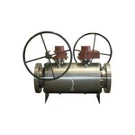
- Bellow Sealed Gate Valve: This type of valve features a bellows seal to prevent leakage of the fluid. The bellows seal design may have a slight impact on the flow path, but in general, modern bellow - sealed gate valves are designed to maintain a relatively high flow capacity. The seal mechanism adds an extra layer of safety, especially in applications where the fluid is toxic or volatile.
- Bellow Sealed Gate Valve: Another variant of the bellow - sealed gate valve. The specific design and manufacturing process of this valve can influence its flow capacity. Some advanced designs may optimize the internal structure to reduce flow resistance and enhance the flow rate.
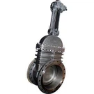
- Pressure Seal Gate Valve: Pressure seal gate valves are designed for high - pressure applications. The pressure - seal design allows the valve to maintain a tight seal even under high - pressure conditions. The flow capacity of these valves is carefully engineered to ensure that they can handle the required flow rates without compromising the sealing integrity.
Choosing the Right API6A Gate Valve for Flow Capacity
When selecting an API6A gate valve based on flow capacity, the following steps are recommended:
- Determine the Flow Requirements: Calculate the required flow rate based on the process requirements, such as production rates, pipeline capacity, and operating conditions.
- Consider the Pressure Differential: Determine the expected pressure differential across the valve. This information is crucial for selecting a valve that can handle the pressure and maintain the desired flow rate.
- Select the Appropriate Valve Type and Size: Based on the flow requirements and pressure differential, choose the right valve type (e.g., full - bore or reduced - bore) and size to achieve the optimal flow capacity.
- Review the Valve's Technical Data: Check the valve's technical documentation, including the flow coefficient ((Cv)) values, to ensure that the valve can meet the required flow rate.
Conclusion
As a leading API6A gate valve supplier, we are committed to providing our customers with high - quality valves that offer excellent flow capacity. Understanding the factors that influence the flow capacity of API6A gate valves is essential for selecting the right valve for your specific application. Whether you need a Bellow Sealed Gate Valve, a Bellow Sealed Gate Valve, or a Pressure Seal Gate Valve, we have a wide range of options to meet your needs.
If you are interested in learning more about our API6A gate valves or discussing your specific requirements, we encourage you to contact us. Our experienced team of experts is ready to assist you in choosing the most suitable valve for your application and to provide you with professional advice and support. Let's work together to ensure the smooth and efficient operation of your industrial processes.
References
- American Petroleum Institute. API 6A Specification for Wellhead and Christmas Tree Equipment.
- Valves Handbook. Industrial Valve Manufacturers Association.
- Crane Technical Paper No. 410. Flow of Fluids Through Valves, Fittings, and Pipe.