There is a direct relationship between flow rate, and flow rate and flow rate are two interdependent quantities. When the flow rate is constant, if the flow rate is large, the flow channel area can be smaller; if the flow rate is small, the flow channel area can be larger. On the contrary, if the flow channel area is large, the flow speed is small; if the flow head area is small, the flow speed is large. If the flow rate of the medium is large, the valve diameter can be smaller, but the resistance loss will be larger and the valve will be easily damaged. If the flow rate is large, it will produce a phasic effect on flammable and explosive media, causing danger; if the flow rate is too small, the efficiency will be low and it will be uneconomical. For highly viscous and explosive media, a smaller flow rate should be used. For oil and liquids with high viscosity, the flow rate should be selected according to the viscosity, generally 0.1~2m/s.
Generally, the flow rate is known and the flow rate can be determined empirically. Commonly used flow recommendations for various media are shown in Table 2-31. By flow rate and volume
The nominal size of the valve can be calculated.
When calculating the valve diameter according to the predetermined medium flow rate, it can be determined by the following formula
Valve flow channel area and flow rate (Figure 1)
In the formula, d is the diameter of the valve mmW - medium mass flow rate kg/hQ medium volume flow rate m3/h; p - medium density kg/m3V medium average flow rate m/s.
The valve diameter is the same, but its structure type is different, and the fluid resistance is also different. Under the same conditions, the greater the resistance coefficient of the valve, the greater the flow rate of the fluid through the valve and the decrease in flow rate; the smaller the resistance coefficient of the valve, the greater/less the decrease in flow rate and flow rate of the fluid passing through the valve. The resistance coefficient of the gate valve is small, only 0.1 Within the range of ~1.5. The resistance coefficient of gate valves with large diameters is 0.2~0.5. The resistance coefficient of reduced port gate valves is larger. The resistance coefficient of stop valves is much larger than that of gate valves, generally between 4 and 7. The Y-shaped stop valve (DC type) has the smallest resistance coefficient, between 1.52. The resistance coefficient of forged steel stop valve is the largest, even as high as 8.
The resistance coefficient of the check valve depends on the structure: the swing check valve is usually 0.8~2, among which the resistance coefficient of the multi-disc swing check valve is larger; the lift check valve has the largest resistance coefficient, up to 12.
The resistance coefficient of the plug valve is small, usually about 04~1.2.
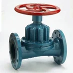
The resistance coefficient of the diaphragm valve is generally around 2.3.
The resistance coefficient of butterfly valve is small, generally within 0.5.
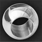
The resistance coefficient of the ball valve is the smallest, generally around 0.1. The resistance coefficient of the above-mentioned valve is the value when the valve is fully open.
1. 6 expansion joints, Dn-200, material: SS310
The inner pipe diameter is DN200 and the hole spacing should be greater than 200mm. Check the data BC HOLE data.
2. Material transfer valve WLF
Make it according to the required size, no problem
3.Ball valve
DN-50 length L=143mm(BC HOLE)
DN-40 length L=133mm(BC HOLE)
4. Check valve
DN40 length L=101mm(BC HOLE)
DN50 length L=117mm(BC HOLE)
Does not match the required length and size, check if it can be used
5.Three-piece ball valve
DN40 length L=110mm(BC HOLE)